![[*]](/l2htmlicons/gif/cross_ref_motif.gif) summarizes the results of
tests involving the
mixtures listed in Table 1. The initial pressure listed
for each shot includes the pressure added by the driver gas. Detonation
initiation or failure of each shot is recorded under ``Go''.
Chapman-Jouguet detonation speeds, as predicted by
STANJAN [Reynolds (1986)], are
reported under D
is that equilibrium predictions of detonation speed are quite accurate.
This relates to the performance of the driver (Section )
as well as the accuracy and relevance of equilibrium calculations.
Of the shots with promptly initiated detonations, the apparent velocity
between pressure transducers 1 and 2 was slightly above the CJ
velocity (0.14% on average),
and the apparent velocity between transducers 2 and 3 exhibited a slight
velocity deficit (0.27% on average). The average drop in velocity was
7.92 m/s. Several photographic examples of soot foils are given in
Appendix and a number of pressure traces are provided in
Appendix G.
summarizes the results of
tests involving the
mixtures listed in Table 1. The initial pressure listed
for each shot includes the pressure added by the driver gas. Detonation
initiation or failure of each shot is recorded under ``Go''.
Chapman-Jouguet detonation speeds, as predicted by
STANJAN [Reynolds (1986)], are
reported under D
is that equilibrium predictions of detonation speed are quite accurate.
This relates to the performance of the driver (Section )
as well as the accuracy and relevance of equilibrium calculations.
Of the shots with promptly initiated detonations, the apparent velocity
between pressure transducers 1 and 2 was slightly above the CJ
velocity (0.14% on average),
and the apparent velocity between transducers 2 and 3 exhibited a slight
velocity deficit (0.27% on average). The average drop in velocity was
7.92 m/s. Several photographic examples of soot foils are given in
Appendix and a number of pressure traces are provided in
Appendix G.
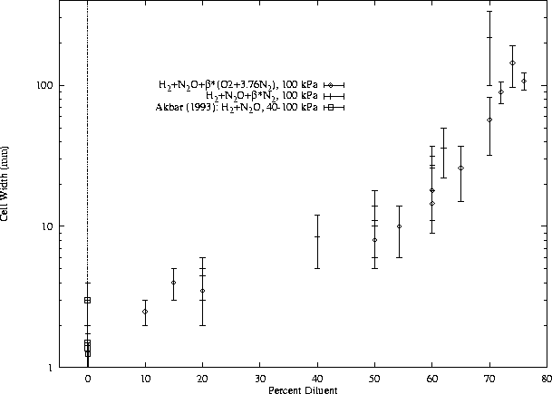
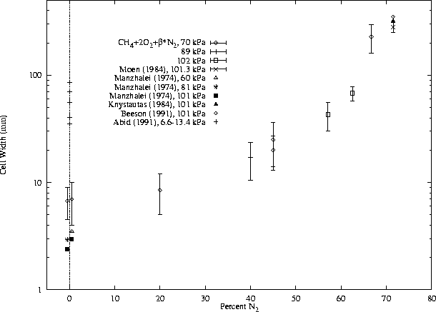
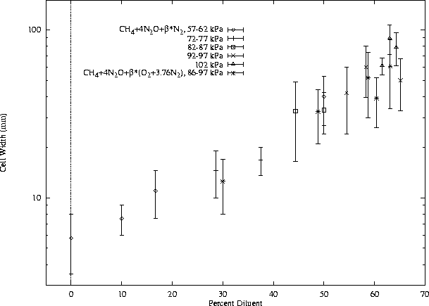
Figures 4 through 11 show the cell-width measurements along with data from the literature. These data are also shown in different form in Section 3.3. Figure 4 shows cell-width measurements of H2-N2O-diluent mixtures from the present work and from a previous report [Akbar and Shepherd (1993)]. Cases with dilution by air and N2 are presented together. Figure 5 shows cell-width measurements of CH4-O2-N2from the present work and a number of other publications ([Moen et al. (1984)], [Manzhalei et al. (1974)], [Knystautas et al. (1984)], [Beeson et al. (1991)]). Note that the data points around 0% N2 have been artificially spread out so they are distinguishable, but they all represent the undiluted case. The data points at 71.5% N2 also represent stoichiometric CH4-air. As described in Section 2.1, higher initial pressures were generally used at higher dilutions, but some data points at low pressure (70 kPa) are shown for both low and high dilution. Figure 6 shows cell-width measurements of CH4-N2O-diluent mixtures from the present work only. No comparable data have been found in the published literature. Five of the tests shown in Fig. 6 used air dilution and the rest were with N2 dilution. Within the range of dilution studied experimentally, little difference is seen between N2 and air dilution. Again, data from a number of initial pressures are shown together.
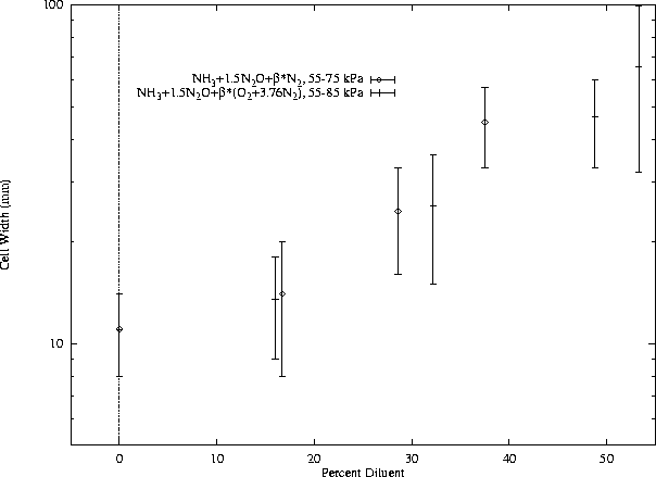
Some data were available from unpublished sources for cell widths in stoichiometric NH3-O2 mixtures diluted by N2 [Bennett (1986)] and these data are shown along with some from the current work in Fig. 7. Figure 8 shows data for stoichiometric NH3-N2O mixtures diluted with N2 and air. As seen in the CH4-N2O data (Fig. 6), little difference is apparent between N2 and air dilution at the levels tested.
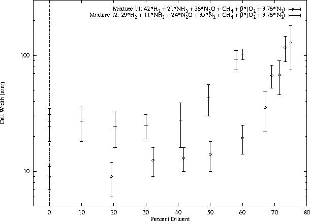
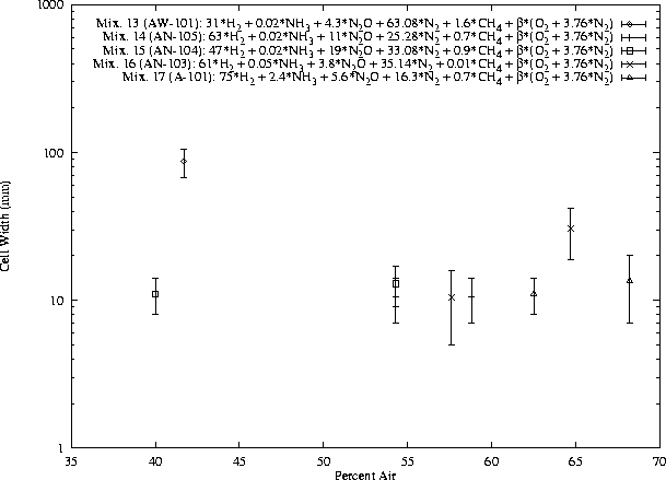
A large number of tests were performed with two versions of SY-101 model tank mixtures with variable air dilution, and these results are shown in Fig. 9. At the lower dilution levels, the initial pressure varied below 1 atm. These data are interesting for the slow increase (and slight decrease for mixture 12) of cell width with increasing air concentration at low dilution. A selection of air dilution cases were tested in other model tank mixtures, and these data are shown together in Fig. 10.
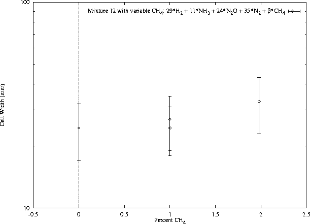
A notable feature of the model tank mixtures under study is the small concentrations of CH4 present. In all experiments and calculations performed so far, the CH4 has been included as specified. However, analysis of the mixtures would be greatly simplified if it were omitted, particularly for chemical kinetics calculations. The number of reactions to be considered could be dramatically reduced (79 reactions and 20 species vs 201 reactions and 45 species) for one standard mechanism. Possible strategies for omitting CH4 from the study include ignoring it, replacing it with a comparable species, or developing some correction scheme based on modeling results. Considering this, a set of experiments with one of the model tank mixtures were performed (without air) with various CH4 concentrations. These results are shown in Fig. 11 which shows a slight increase in cell width with methane concentration in the range of 0-2% CH4.
Some of the model tank mixtures contain very small quantities of NH3, which may be insignificant. However, since some mixtures do contain substantial concentrations of NH3, any gains made by omitting it would be limited.