
|
|
|
Pulse Detonation EnginesPDE Information | Resources | Publications | Links | A pulse detonation engine is an unsteady propulsive device in which the combustion chamber is periodically filled with a reactive gas mixture, a detonation is initiated, the detonation propagates through the chamber, and the product gases are exhausted. The high pressures and resultant momentum flux out of the chamber generate thrust. Quasi-steady thrust levels can be achieved by repeating this cycle at relatively high frequency and/or using more than one combustion chamber operating out of phase. A brief introduction to pulse detonation engine issues and research at Caltech is available in a (PDF 1.9 Mb) presentation prepared by Eric Wintenberger. PDE research at Caltech is being carried out in the Explosion Dynamics Laboratory as part of our overall studies into fundamental processes in transient combustion. The present work builds on two decades of research into flame and detonation propagation in various gaseous mixtures. The PDE-related research topics that have been studied in our lab are:
Detonation Structure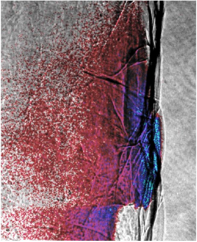 Combined schlieren and PLIF image of propagating detonation in 20 kPa 2H2+O2+17Ar.
Direct experimental observations of the reaction zone structure in propagating detonations have been made using planar laser induced fluorescence (PLIF) of the OH radical. For the first time, images were obtained with sufficient spatial resolution to resolve 'keystone' features in the reaction front due to variations in the lead shock strength. Experiments were carried out in the 150x150 mm test section of the detonation tube at Caltech. OH molecules were excited using an excimer-pumped dye laser tuned to 284.008 nm, halfway between the transitions (1,0) Q2(8) and (1,0) Q1(9). An 80 x 0.3 mm planar light sheet was formed and entered the test section through a quartz window in the end flange. The induced fluorescence, filtered with a 313 nm filter (10 nm FWHM), was collected by an ICCD camera positioned at 90 deg to the direction of propagation of the detonation, visualizing a cross-section of the flow. Experiments performed with a partially blocked laser light sheet confirmed that the natural chemiluminescence in the images was negligible. Some simultaneous Schlieren images were obtained. Stoichiometric hydrogen-oxygen mixtures at 20 kPa were studied with different diluents to examine the effect of cell regularity on reaction zone structure.   Keystone structures were observed for all mixtures. Mixtures with argon dilution showed much more regular structure than mixtures diluted with nitrogen. Shock and detonation polar analysis was used in the vicinity of the triple point to determine that the keystones are bounded by the reaction zones behind the incident wave and Mach stem and by the shear layer. A particularly clear example of a keystone in a hydrogen-oxygen-argon mixture at high dilution is shown. The combination of very regular detonation structure and persistent experimentation resulted in obtaining this image. Work carried out at Caltech by Florian Pintgen and Jo Austin (now at UIUC)
Detonation Diffraction
Shadowgraph of critical detonation diffraction in 100 kPa 2H2+O2. The re-initiated detonation is propagating spherically outward and sweeping back into the shocked reactants. The problem of a self-sustaining detonation wave diffracting from a tube into an unconfined space through an abrupt area change is characterized by the geometric scale imposed by the tube and the reaction scale of the detonation. Previous investigations have shown that this expansion associated with a detonation transitioning from planar to spherical geometry can result in two possible outcomes depending upon the combustible mixture composition, initial thermodynamic state, and confining geometry. Competition between the energy release rate and expansion rate behind the diffracting wave is crucial. The subcritical case is characterized by the rate of expansion exceeding the energy release rate. As the chemical reactions are quenched, the shock wave decouples from the reaction zone and rapidly decays. The energy release rate dominates the expansion rate in the supercritical case, maintaining the coupling between the shock and reaction zone which permits successful transition across the area change. In the present investigation an analytical expression has been derived from a model of detonation diffraction through an abrupt area expansion which permits the calculation of critical conditions which separate the sub-critical and super-critical regimes. This model is based on the critical decay rate concept developed at Caltech to enable the prediction of critical energies in blast initiation. This model is based on a competition between the sustaining effect of energy release and the quenching effect of unsteadiness. 
The critical diffraction conditions were calculated for fuel-oxygen and fuel-air mixtures with varying stoichiometry, initial pressure, and diluent type (argon, carbon dioxide, helium, nitrogen) and concentration for hydrogen, ethylene, and propane fuels. Results from the critical diffraction model were compared against experimentally-determined critical conditions for diffraction from a circular cross section and found to be in complete qualitative agreement, and in quantitative agreement to within the uncertainty associated with the calculation of model parameters and the experimental measurements. Work carried out at Caltech by Eric Schultz, now with USAF Detonation Cell Width Measurements
A detonation tube facility was originally designed and constructed by Raza Akbar, Pavel Svitek, and Mike Kaneshige. The GALCIT detonation tube is 7.3 m (24-ft) long, 280 mm (11-in.) inner diameter and constructed of 3 cast stainless steel (304) segments joined together by flanges and high-strength fasteners. The tube is equipped with a gas control system to precisely create test mixtures of fuel, oxidizer and diluents; a gas mixer system; a vacuum system; instrumentation and data acquisition systems. Gas composition is determined by the method of partial pressures. 
A short slug of oxygen-acetylene mixture is injected just prior to initiation as booster charge. The driver is initiated by an exploding wire created by discharging a capacitor through a copper wire. The driver produces a blast wave with an peak amplitude of about 0.4 MPa (60 psig) at the first pressure transducer, sufficient to initiate mixtures with cell widths up to 400 mm. Detonation pressure and velocity are measured with piezo-electric pressure transducers. For the PDE engine project, many parts of the GDT were replaced or modified. The flanges and grooves were strengthened and the tube pressure-tested to 3000 psi. The tube and flanges are equipped with heaters and PID controllers so that the tube could be maintained at temperatures up to 120C. This is in order to study fuels such as JP10 and Jet A in the vapor phase. Selected results for JP-10 and JP10/HC mixtures are given in this Excel spreadsheet Some results as of August 2001 - Note CDL data point has been corrected. 
Work carried out by Tony Chao, Florian Pintgen, and Jo Austin
Vapor Pressure in JP-10
Vapor pressure measurements are needed in order to carry out detonation cell width experiments with warm JP-10 vapor. In order to assure that only vapor is present in the detonation tube, the tube has to be heated above the saturation temperature corresponding to the partial pressure for that composition. Since reliable measurements were not available in the open literature for the temperature range of interest, we carried out measurements in our laboratory using techniques that were developed for measuring the vapor pressure of aviation kerosene (Jet A). The numerical values are given in an Excel spreadsheet. Work carried out by Eric WintenbergerDetonation Initiation and Impulse Measurement
Previous work on deflagration-to-detonation transition (DDT) has demonstrated that for fuel-air mixtures, the transition distance or time can be extremely long for plain tubes. Obstructions (internal obstacles) are required in order to obtain a detonation within a short tube. The effect of these obstacles and the DDT process on the impulse obtained from a single tube have not been previously measured. Direct measurements were made of the impulse delivered by a DDT-initiated detonation or a fast flame. The impulse was determined by measuring the displacement of a ballistic pendulum in which a tube was suspended from the ceiling by steel wires. 
The combustible mixture, initially contained in the tube by a thin diaphragm, was ignited by a spark at the thrust wall. Combustion products were free to expand out from the tube into an unconfined volume. Pressure histories were recorded, including the pressure at the thrust wall which was then integrated for comparison with the ballistically-determined impulse.  Approximately 100% more impulse was produced when a highly diluted mixture could be made to transition to detonation by the presence of obstacles than in the case of a fast flame. In mixtures in which DDT occurred in the absence of obstacles, the inclusion of obstacles reduced the impulse measured by about 25%. It is important to note that in these cases, the impulse derived from the thrust-wall pressure trace overpredicts the impulse measured by the ballistic pendulum by a factor of two since the pressure integration neglects the momentum lost to drag over the obstacles. 
Experimental impulse measurements for detonations were compared with analytical predictions and with numerical simulations. The analytical model approximates the pressure history by two regions: an approximately constant pressure region which begins with the passage of the Taylor wave and ends with the arrival of the first characteristic of the reflected wave (usually an expansion) at the thrust wall, and a second region which models the pressure decrease through the remaining reflected wave . The similarity solution for the Taylor wave and dimensional analyses have been used to predict the measured impulse if the thermochemical properties of the mixture are known. This model requires some nondimensional constants which are obtained by integrating the appropriate region of experimental and numerical pressure traces. Work carried out by Jo Austin, Eric Wintenberger, Marcia Cooper, Scott Jackson Detonation Tube Structural Response
Previous work at Caltech on mechanical response of detonation tubes has emphasized the importance of flexural waves and the possibility of resonant excitation of flexural waves by detonations or shock waves. Laboratory measurements, analytic solutions of elastic equations, and numerical solutions to finite-element models have all demonstrated that strains up to 4 times higher than the static values can be produced . An apparatus is currently being set up to investigate the fracture behavior and failure criteria of pre-flawed and thin-walled tubes under single cycle detonation loads. Preliminary studies involve measurements of crack propagation speeds and crack tip stability. These will be followed by high-speed photography that will visualize the displacement field near the crack-tip. 
Finite-element simulations of flexural wave excitation by traveling loads have been carried out to determine the growth of the wave amplitude as a function of distance and wave speed. The image shown above is a link to a movie showing the propagation of flexural waves.
Work carried out by Tony Chao and Patrick Hung |

